

 |
 |
 |
|
|
|
|||||||
| Electrics & Lighting All discussions related to bike electric, lights, bulbs, fuses and wiring. |
 |
|
|
Thread Tools | Display Modes |
|
#
1
|
|||
|
|||
|
custom dashboard xt660z
Hi, guys
i own xt660z I am mounting replacement speedometer imo-100r50, thats for speed, i have check service guide for bike, theres no internal things how meter works, I would like to display warning lights, rpms, fuel level somehow as well. I dont want to dissasemble original speedometer just in case now, but i might do it if no other option. Have somebody done it before? Any guidance? Thanks. |
|
#
2
|
|||
|
|||
|
go update:
I am going for trailtech voyager, it measure coolant temperature (it own sensor), rpm from spark plug. Whats doable is gear indicator (dont need it now) Question remains...: how to measure fuel level (at least reserve?) i just had tank off, tried to mesure those 4 wires, but wasnt able to get to know how does they work. Anybody did something similar? Any help? |
|
#
3
|
|||
|
|||
|
Quote:
What you�d have to work out first is the range of resistances produced by the sender across the range of float positions. There is no test given (or resistances) for the fuel sender in the workshop manual, but they�d be easy to work out with a multimeter either with the fuel pump assembly removed from the tank, or by leaving it in position and filling the tank 1 litre at a time from empty. Measure between the green and black wire's terminals on the sender connector on the fuel pump assembly. You could then try and find a gauge that works within that range which might be a bit tricky (?), or get a cheap LED or LCD voltmeter and use the displayed voltage to indicate how full the tank is. The voltmeter option would probably be the simplest and neatest way to read fuel level. They are really cheap to get on ebay (something like this) and are small enough to mount in a variety of positions. It would give you a number (the voltage) which you could calibrate against the fuel level. On a lot of them the display turns off below a minimum voltage, which would/could give you a good low fuel level warning or indication of reserve. Not sure which way the fuel sender pot works on the Z, but more often than not fuel senders have no (or minimum) resistance when the tank�s full and resistance increases as it empties. Based on that assumption, you�d get 12-14V (depending on engine running or not) when the tank was full and it would drop to whatever voltage the pot�s resistance will allow when the tank was empty. If you wanted to have a precise/constant full reading (that didn�t vary with charging voltage) you could easily fit a cheap voltage regulator/limiter to the supply to the meter so that the maximum voltage it receives from the battery would be 12.5V at 0 resistance. If you didn�t want a numerical display, you can also get LED bar type voltmeters that are quite small, which would make an ideal fuel gauge. Hope this gives you some inspiration, ideas and a few things to try� |
|
#
4
|
|||
|
|||
|
Quote:
I do know how potentiometer basically works, i just dont get 2 wires. I tried to tap those 2 no voltage in them. (Green and black) i got dash disconnected though If i feed 12v into green in potentiometer i would need another wire eher i can mesure output voltage, black is griund i suppose. Red and black is voltage for fuel pump? If i can mesure voltage i can set rest up. I programmed few arduinos, will do it that way. |
|
#
5
|
|||
|
|||
|
Quote:
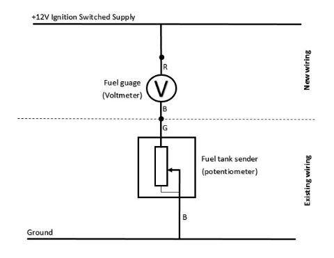
You should (as you say) be able to create a new (ignition switched) 12V supply to the sender and then to earth. With the new voltmeter/gauge (or whatever you decide) sitting between the supply and the sender. Something like this... +12V -----> gauge -----> sender -----> earth Good luck! Keep us posted... |
|
#
6
|
|||
|
|||
|
Quote:

What I do get is potentiometer with 3 wires. You supply voltage to one, one is ground and rest is altered voltage. I got green and black wire. I assume black wire is ground, not sure but almost. (theres red and black wire, if i unplug those bike wont run long, both blacks are same) (GR, BL, RD) I have ignition switched 12v +. (IS12) I have hand voltmeter with 2 (red and black) connections. (V+, V-) What to connect where? IS12 -> V+ ? (it will measure 12V, we need to run it thru potentiometer first?) IS12 -> GR ? (if BL is ground, i dont get how i will measure anything with coltmeter here either) |
|
#
7
|
|||
|
|||
|
The bike won't run without the red and black pair of wires connected up to the loom - they are for the fuel pump.
I think you may be confusing yourself a little with the three-wire potentionmeter connection issue! 
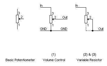
In a basic sense there are basically three way to wire a pot. (1) 3x wires - input, wiper and ground, which is used as a volume control as it will be "off" when grounded. (2) 3x wires - input with wiper and ground connected together, so essentially it only has two connections as wiper and ground are linked. (3) 2x wires - only using the input and wiper, which achieves a similar effect to (2), making a straight forward variable resistor. With this two connection method, whichever end of the track you apply the input will determine which way the resistance changes, either increasing or decreasing as the wiper moves along the track. 
The fuel sender pot will be either (2) or (3). Regardless of which, it will only have two wires emerging from it - one (green) is effectively the input (12V) and one (black) the output (off the wiper) going to ground. To connect a gauge (or voltmeter to act as a gauge) then it should be wired as in the diagram below. Remember you need to provide a new ignition switched 12V supply as the existing (green) wire supplying the sender comes from the dash panel (which you haven't got anymore!) 
Just to reiterate, I do not know which way the fuel sender on the Tenere tracks (either up or down in resistance with float movement), I have not tested this. I also do not know what range of resistances it produces, as I haven't tested that either. I would strongly recommend, before doing any of the above, setting your multimeter to 1K ohm and connecting the probes to the green and black wires on the sender unit and measuring the change in resistance as you add/remove fuel from the tank (unless you want to take the whole pump assembly out and move the float manually). |
|
#
8
|
|||
|
|||
|
GW, greenwhite dash wire seems it. It measure 90-100 ohms roughly, I tried to supply 12v over there.
It measure 12.5, but when bike its started its 13.6v. Going to try to empty tank to see whats happening. Whats IM excited about is I managed to measure neutral light. Its ignition switched +12v and variable ground on GL (light green) wire. Shaping up nicely. Maybe engine fault would be nice, and temp warning. YL (yellow) with BL (black) as ground provide +12v if high beam is activated. Last edited by mathewst; 18-05-14 at 20:09. |
|
#
9
|
|||
|
|||
|
Quote:
resistence however yes. Empty tank is 140 and Full tank 20 ohms. (greenwhite and black wires) These are readings without bike started. What is a problem though, when I start the bike, theres some potential messing things up and I cant read resistance well anymore. (even polarity of the multimeter changes reading) I dont get this. I should maybe try with cables directly at the tank. Last edited by mathewst; 18-05-14 at 20:11. |
| Sponsored Links |
|
#
10
|
|||
|
|||
|
Quote:
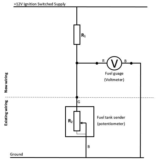
One thing you can do to help get a broader range of voltages produced by the potentiometer (sender) and make them easier to detect is to wire in a second resistor in series with the pot, but connect the gauge (voltmeter) between the new resistor and the pot to take your readings. An additional 100ohm resistor should give you 2V when the pot is giving 20ohms and 7V when its giving 140ohms. Here's the circuit: 
You can experiment with different resistors to get the voltage readings you want/need. All you need to know is the formula: V(in) = V(out)x(R2/R1+R2) [where R2 is the pot and R1 is the series resistor] This setup is known as a voltage divider network. Haven't got time to explain it now, but this site explains the theory in simple terms. |
 |
| Thread Tools | |
| Display Modes | |
|
|