Home

Go Back   .: XT660.com - The #1 XT660 Resource :. > XT660 Tech Section > Performance Modifications & Enhancements > Electrics & Lighting
FAQ Calendar Search Today's Posts Mark Forums Read Main site

Google

Electrics & Lighting All discussions related to bike electric, lights, bulbs, fuses and wiring.

Reply
 
Thread Tools Display Modes
  # 1  
Old 11-09-13, 16:45
bikemad195 bikemad195 is offline
XT-Moto SuperStar
 
Join Date: Nov 2012
Location: hull uk
Posts: 313
bikemad195 is on a distinguished road
Post 30amp aux supply relay help?

hi all, i have a question about relays. ok so i am going to put a proper aux power feed for big draws e.g handle bar grips and cig socket etc . ok so ive got a 30 amp relay (link below) and i am just trying to figure out the trigger circuit which im obs going to run off something silly e.g side ligh circuit etc but the question i have is if i was to kill the relay somehow wouldn't it also kill the appliance that trigger circuit originally powered as the way i currently see it i would have to break this trigger cable and run it in one side of the relay and back out the other therefore relying on the relays components giving it a weak spot if the relay decided to be a ***** ?and creating a break in the original circuit

bike a xt660x

http://www.ebay.co.uk/itm/3606094283...84.m1497.l2649
__________________
Yamaha xt660x 2009 blue/gold mods= iridium plug, stage1+2, removed snorkel, blocked ais, akrapovric pipes, power commander pc3usb (pre made map), adjusted tps, dynojet 02 optimiser 30amp aux relay, smoked puig screen, oxford heated grips and brembo carbon ceramic pads, rfx 30mm bar raisers, puig long adjustable leavers, plus much more and a cheep �30 alarm which stopped it been stolen
Sponsored Links
  # 2  
Old 11-09-13, 19:04
Pleiades Pleiades is offline
XT-Moto SuperStar
 
Join Date: Aug 2010
Location: North Norfolk
Posts: 5,320
Pleiades is on a distinguished road
Quote:
Originally Posted by bikemad195 View Post
the way i currently see it i would have to break this trigger cable and run it in one side of the relay and back out the other therefore relying on the relays components giving it a weak spot if the relay decided to be a ***** ?and creating a break in the original circuit
You must not split the original circuit and feed the whole thing through the relay - this will be a recipe for disaster!

You take a +12V feed to trigger the relay off the side light circuit (a spur or "T") by "tapping" into it and connecting this spur to one of the trigger/switching terminals on the relay. You can use a Scotchlok to this, or strip back the insulation and solder on the spur. The opposite trigger/switch terminal on the relay must be connected directly to ground (earth) with another wire. The only connection between side light circuit and relay should be the incoming +12V feed.

The load circuit (for the accessories) can then be passed from battery (via a fuse) throught the load termainals on the relay (in one, out the other) to the accessory, and then from the accessory to earth.

Below is a wiring diagram. Ignore the fact that the load circuit is lights (could be any accessory). Note the only connection with the existing loom on the back is the single feed from the side light circuit.


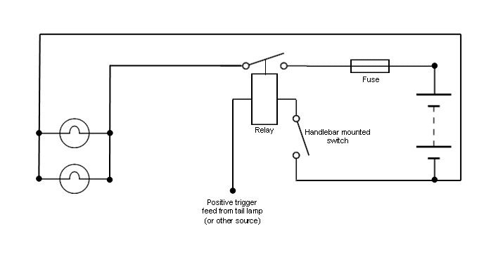
Most good relays only draw a miniscule current of about 3-5mA to trigger the relay, so if wired correctly it will never harm the original circuit the spur is taken from.

Last edited by Pleiades; 11-09-13 at 21:48. Reason: dodgy spelling
  # 3  
Old 12-09-13, 02:43
bikemad195 bikemad195 is offline
XT-Moto SuperStar
 
Join Date: Nov 2012
Location: hull uk
Posts: 313
bikemad195 is on a distinguished road
Quote:
Originally Posted by Pleiades View Post
You must not split the original circuit and feed the whole thing through the relay - this will be a recipe for disaster!

You take a +12V feed to trigger the relay off the side light circuit (a spur or "T") by "tapping" into it and connecting this spur to one of the trigger/switching terminals on the relay. You can use a Scotchlok to this, or strip back the insulation and solder on the spur. The opposite trigger/switch terminal on the relay must be connected directly to ground (earth) with another wire. The only connection between side light circuit and relay should be the incoming +12V feed.

The load circuit (for the accessories) can then be passed from battery (via a fuse) throught the load termainals on the relay (in one, out the other) to the accessory, and then from the accessory to earth.

Below is a wiring diagram. Ignore the fact that the load circuit is lights (could be any accessory). Note the only connection with the existing loom on the back is the single feed from the side light circuit.


Most good relays only draw a minuscule current of about 3-5mA to trigger the relay, so if wired correctly it will never harm the original circuit the spur is taken from.
cheers for the come back so basically for the low side of the relay i take a t off the trigger circuit and put that on one terminal and then earth the other terminal out ? also basically once i have done this i will obvs have a 30amp switch circuit for my load i want to run a cable of this and make some sort of live positive terminal so i can put more then once device through it e.g the grips and aux socket and maybe some other stuff. any ideas what i can use to create these easy accessible terminal so i can use it as a junction for all my auxs e.g so i can put them all on to ring terminals and then connect them to the 1 big feed from the relay ? (cheers for youre help with this lol i feel silly asking this sort of thing when im technically a qualified car mechanic lol )
__________________
Yamaha xt660x 2009 blue/gold mods= iridium plug, stage1+2, removed snorkel, blocked ais, akrapovric pipes, power commander pc3usb (pre made map), adjusted tps, dynojet 02 optimiser 30amp aux relay, smoked puig screen, oxford heated grips and brembo carbon ceramic pads, rfx 30mm bar raisers, puig long adjustable leavers, plus much more and a cheep �30 alarm which stopped it been stolen
  # 4  
Old 12-09-13, 07:45
Pleiades Pleiades is offline
XT-Moto SuperStar
 
Join Date: Aug 2010
Location: North Norfolk
Posts: 5,320
Pleiades is on a distinguished road
Quote:
Originally Posted by bikemad195 View Post
any ideas what i can use to create these easy accessible terminal so i can use it as a junction for all my auxs e.g so i can put them all on to ring terminals and then connect them to the 1 big feed from the relay ?
The easiest way is to fit a single pole terminal block or "buzz bar" like this sort of thing...


You'll need to put it in a box to prevent anything shorting. Better still is to fit a covered fuse box, which will enable you to fit a correctly rated fuse individually for each accessory you add...


Connect load feed to a terminal on one side and then link it across to all the others on that same side using 30A cable and crimp-on spade connectors. Then the terminals on the opposite side all become outputs with their own fuse.

Best type of fuse box is a distribution type, one with a single input like this one (it even has an LED indicator to show whether each output is live and if a fuse has blown!)


You connect the load from the relay to the terminal post (nut) and then you gain six outputs which each have spade terminals and their own fuse.

Good place for all things auto-electrical here
  # 5  
Old 12-09-13, 15:31
bikemad195 bikemad195 is offline
XT-Moto SuperStar
 
Join Date: Nov 2012
Location: hull uk
Posts: 313
bikemad195 is on a distinguished road
Quote:
Originally Posted by Pleiades View Post
The easiest way is to fit a single pole terminal block or "buzz bar" like this sort of thing...


You'll need to put it in a box to prevent anything shorting. Better still is to fit a covered fuse box, which will enable you to fit a correctly rated fuse individually for each accessory you add...


Connect load feed to a terminal on one side and then link it across to all the others on that same side using 30A cable and crimp-on spade connectors. Then the terminals on the opposite side all become outputs with their own fuse.

Best type of fuse box is a distribution type, one with a single input like this one (it even has an LED indicator to show whether each output is live and if a fuse has blown!)


You connect the load from the relay to the terminal post (nut) and then you gain six outputs which each have spade terminals and their own fuse.

Good place for all things auto-electrical here
that's just the perfect piece of kit. once again THANKS for you're help .ash
__________________
Yamaha xt660x 2009 blue/gold mods= iridium plug, stage1+2, removed snorkel, blocked ais, akrapovric pipes, power commander pc3usb (pre made map), adjusted tps, dynojet 02 optimiser 30amp aux relay, smoked puig screen, oxford heated grips and brembo carbon ceramic pads, rfx 30mm bar raisers, puig long adjustable leavers, plus much more and a cheep �30 alarm which stopped it been stolen
Reply

Tags
aux relay

Thread Tools
Display Modes

Posting Rules
You may not post new threads
You may not post replies
You may not post attachments
You may not edit your posts

BB code is On
Smilies are On
[IMG] code is On
HTML code is Off

Forum Jump


All times are GMT +1. The time now is 23:07.
Powered by vBulletin® Version 3.8.11
Copyright ©2000 - 2019, vBulletin Solutions Inc.

  XT660         Archive   Main site


Footer
vBSkinworks Top