

|
|
|
|
|
|||||||
| Electrics & Lighting All discussions related to bike electric, lights, bulbs, fuses and wiring. |
 |
|
|
Thread Tools | Display Modes |
|
|
|
#
1
 14-11-09, 13:20 14-11-09, 13:20
|
|||
|
|||
|
Fitting XTX BikeVis Bullets
For any of those who may be interested. I don’t pretend to have the skills of some of the people on this forum but I have gained some modest experience. I still remember when I had my CG125 and no clue. Adjusting the chain tension was a slightly nervous adventure, never mind stripping the drum brakes (remember them) to clean them out and check the shoes (like pads but much bigger). Making the decision that I could give it an oil change and basic service was a big step, and most of this was only possible due to people who were prepared to give me a hand and some instruction. Anyway this is intended to be a how too for the nervous novice who, like me, may find the courage if armed with a set of idiot instructions.
If you think that this is too much, more text explanations needed, less or more pictures then constructive criticism welcome. I decided to get some of those rather fetching Bike Vis Bullet lights to make myself more visible. http://www.bikevis.com/discount-xt660.html. This is my record of the installation. Hopefully it will be helpful to anyone wanting to do the same and isn’t sure. Mine are on now but if anyone has any suggestions or tips that may be an improvement for others then chip in. I decided to mount mine on the widest part of the fairing to give the black bike a bit more width and presence at night. First with the fairing on the bike I used a spirit level to make a horizontal guide mark so that I could orient the fairings when I took them off the bike to work on. I knew I would be mounting the lights with the fairings removed and wanted them horizontal to the bike. 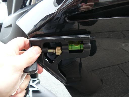
Next the fairings came off and inside where it was warm. I knew I wanted the light mounted far enough back that the wire would be behind the bracket that mounts the fairing pieces you can see from the front, either side of the engine. A quick check confirmed that 40mm would be just right. 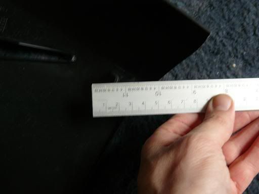
I placed the fairings down with the front facing each other. I then used a rule to make sure that they were horizontal to each other using the guide lines from stage one and measured 40mm back from the edge of the outside top of the panel. 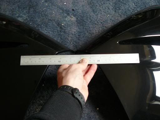
Then I conformed the width of the wires for the hole that would be needed. 4mm 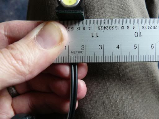
Here you can see the hole from the inside of the panel. Positioned just back from the bracket. 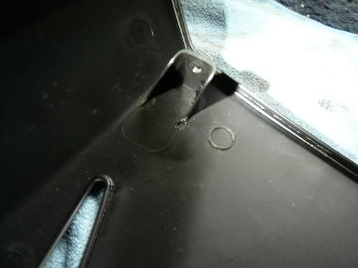
Light mounted on the outside of the panel. I don’t think this looks bad on the black panel. Others may think it was too obvious on a panel of another colour. I’m happy with this. 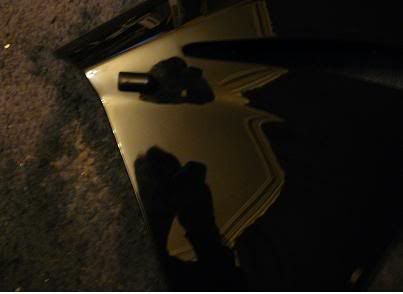
I knew that after fitting these, if I wanted to make taking the fairing off simple, I would need to break the wire and add a plug. I found some good connectors from these people. http://www.vehicle-wiring-products.e...connectors.php . The connectors come separated and you build them your self as the spade connectors need to be crimped to the wire before being pushed into the socket. The female spades go into the wire using the male socket and visa versa. 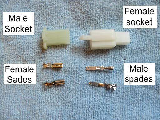
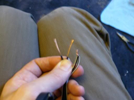
I cut the wire at about 60mm, so it wasn’t hard up against the fairing and I could move the fairing a little before having to disconnect the plug. Strip about 5mm of insulation from the wire and then crimp the inside tabs of the spade around the exposed wire and the outside tabs around the insulated wire. The spade connectors only lock into the socket one way, and I made sure that the spades were ‘the right way round’. By this I mean that when mounted in to the socket the locking tab of the socket wasn’t facing the fairing. This is the spades on the cut wire. 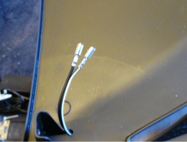
The socket simply pushes on and locks against tabs on the spades. 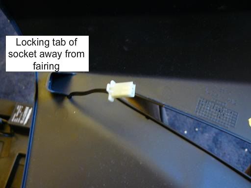
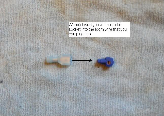
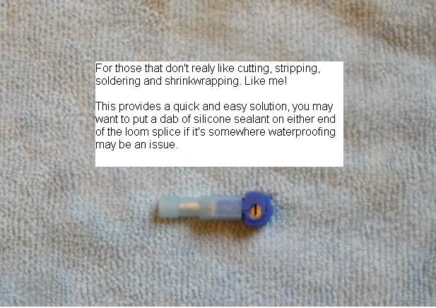
That’s the lights mounted onto the fairing panels and I’m happy so far. I wasn’t sure just how much wire I would need to reach to the loom but I was sure I had more than I needed and didn’t really want the excess. So I decided to connect to the loom with the wire I had cut off and then run it where I needed to connect to the light, add a little for safety and cut the excess. Now I don’t really get on with cutting into my bike loom and soldering it back together with heat shrink to protect the join and all that. Probably just not enough experience. So I took the cowards way out and got some of those neat little tap connectors for splicing into wires (I ordered them with the connector blocks, http://www.vehicle-wiring-products.e...connectors.php). I went with the second type as the join was removable and I wanted to try them. It seemed easier to squeeze two wires onto the splice using this as well. 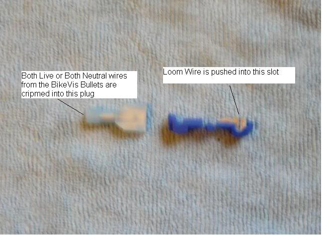
Last edited by Bishop0151; 15-11-09 at 14:08. Reason: Swapped BikeVis link for forum discount link, thanks Uncle Ricky |
|
#
2
14-11-09, 13:25
|
|||
|
|||
|
On the BikeVis wiring the all back wire is your neutral, and the black with white is your live. It is important that you keep track of that. If you get these mixed if they just wont work, or you may even blow the LEDs. You may as well connect both lights to the same splice. I stripped about 20mm, doubled it over and then twisted together both lives, and then both neutrals.
The exposed wire was long and thick enough to fit into the crimping collar of the tap connector plug. One went on each set of wires. 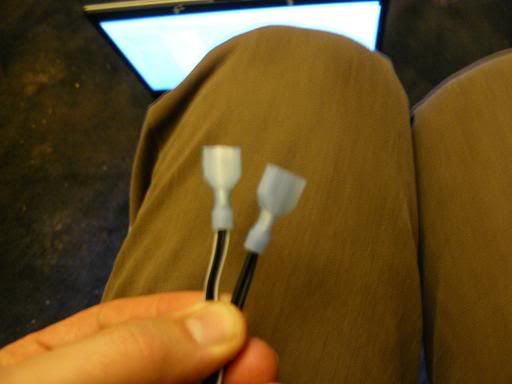
I decided to run the lights from the same feed as the parking light so they would be on as soon as the ignition is on. I’d already replaced this with an LED alternative so it isn’t drawing anywhere near the amps intended and has plenty to spare. I took the headlight off to find the parking light wire and decided I didn’t want to put the taps on the exposed section right near the headlight. The black wire is found all over the loom and is a common colour for the neutral wire. Almost all the other wires will be live wires that are colour coded so you can tell what piece of equipment they supply. Someone had to explain this to me once. (Would it have killed Yamaha to use colour on the wiring diagrams!) 
I cut away some of the loom covering and pulled out the parking light wires so I could place the taps below the ignition barrel. I then taped up all the other wires and clipped the taps in place. At this point I realised that it may be difficult to tell which one was the neutral once it was taped back up. So I took a marker and coloured the neutral tap and plug the common black colour and taped the wires back to the loom. 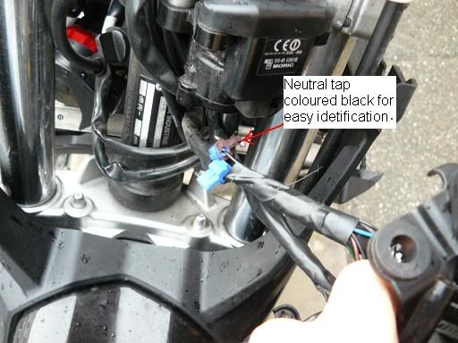
The wires were connected and sent either side of the back of the steering column and the headlight was put back in place. I was able to use cable ties that were already in place to rout the cables where I wanted them without them being in the way of anything or near hot places. Left Hand Side routing 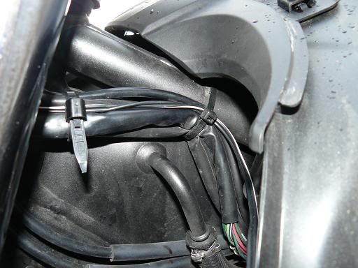
Right Hand Side routing 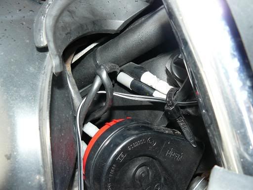
I then brought the wire to were it would connect to the fairing, baring in mind that I already had 60mm of excess on the fairing I didn’t really need much here. 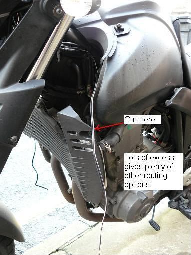
Trim the wires and crimp on the spade connectors. Here I found that the connectors that I had differed. The females crimped without problem but after having a test pull of the male I pulled it off (fnarr fnarr). The stripped wire was a little thin to crimp properly into the male. So I stripped of an extra 5mm and doubled up the stripped wire to make it thicker and this was easier to get a good solid fix on the spade. I’ve made this mistake before and thought everything was crimped in place, put the spades into the plug and connected things up. The first time a little strain was put on the plug all the wires popped out or the spades (Much swearing ensued). REMEMBER the plug will only fit on one way and you have to make sure the positive and neutral wires from both sides of the plugs match up. Keep this in mind when you put the spades into this side of the connector block. While you’re here a little petroleum jelly or silicone waterproofing wouldn’t hurt. 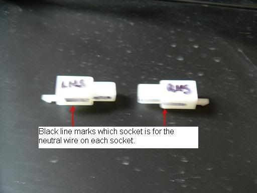
Connect everything up, mount your fairings, hold your breath and switch it on. IT WORKS! Night time picture to follow. 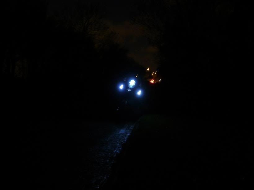
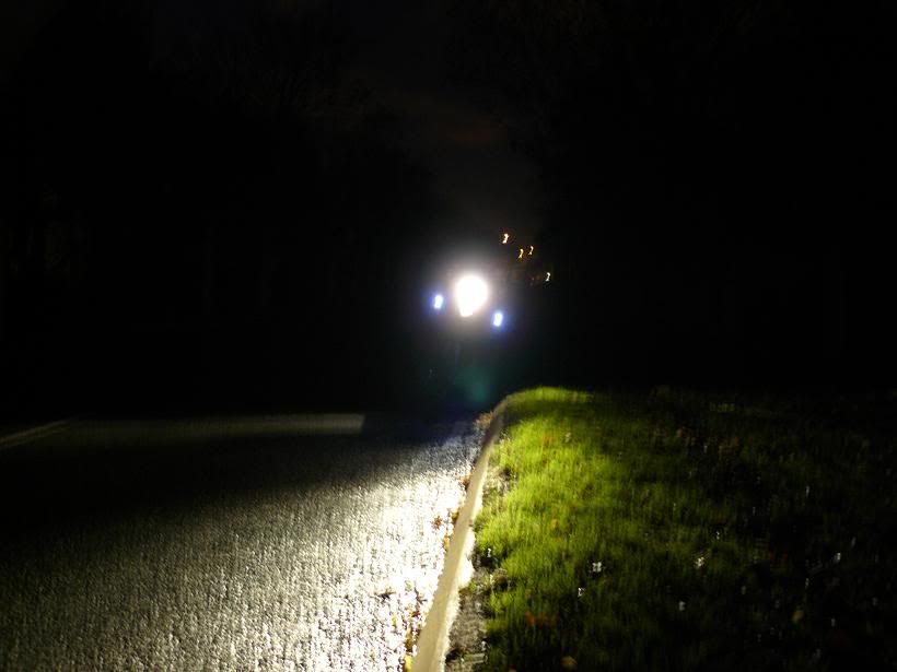
Reward yourself with a beer, it’s in the BikeVis instructions! Unfortunatly I mistimed this job due to rain and finished at 10:30 on a Saturday morning rather than Friday evening. Beer postponed  . .
It's taken me longer to put these instructions together than do the work. If you have everything you are going to need before hand then it should take 1-1.5 hours. Last edited by Bishop0151; 14-11-09 at 20:06. Reason: Added nightime pictures after a beer |
|
#
3
14-11-09, 15:25
|
|||
|
|||
|
Nice work and a great idea (for me anyway, not seen these before)

Might get me a set and mount them on the handguards. Thanks 
__________________

|
|
#
4
14-11-09, 17:14
|
|||
|
|||
|
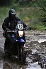
Excellent write up. I fitted mine like yourself at the widest point on the tenere and about door mirror height on cars so they can see you, mine have been on now for a few months. If you do connect the wires the wrong way you wont blow them they just won't work.
that is mine right at the bottom
__________________
 :tenere:


Mods, Oxford heated grips, Givi Rack and top box, Stage 2 DNA filter and top, 02 sensor eliminator, Metal Mule taller screen, Seat hump trimmed off, .KEVS FUEL MOD (THE 1ST ONE FOR THE TENERE) , Extra fuse box, 12volt plug in socket, Zumo550 sat nav, , Barkbusters What Bill Clinton REALLY said to Monica Lewinsky was: "Sack my cook" Sadly Bike now sold 11/6/11 |
|
#
5
14-11-09, 19:35
|
|||
|
|||
|
Quote:
|
|
#
6
14-11-09, 20:07
|
|||
|
|||
|
I was thinking about getting some of these....
Like you said, having a blue bike I would try and mount them somewhere that they can't be seen, but I reckon it would probably look quite cool on a black one! I would have soldered and heatshrinked all the wire joins. (I personally think it would well be worth your time practicing and practicing soldering wires and components until confident. I quite enjoy soldering now! lol) I think your guide was very good, not vague and has lots of informatively annotated pictures 
I alway plan to make guides for the mods I do (on other things too, not just bikes), I take the photos, but never get round to writing them up lol. So yeah......good stuff! Harry |
|
#
7
15-11-09, 00:53
|
|||
|
|||
|
__________________
:tenere:
Mods, Oxford heated grips, Givi Rack and top box, Stage 2 DNA filter and top, 02 sensor eliminator, Metal Mule taller screen, Seat hump trimmed off, .KEVS FUEL MOD (THE 1ST ONE FOR THE TENERE) , Extra fuse box, 12volt plug in socket, Zumo550 sat nav, , Barkbusters What Bill Clinton REALLY said to Monica Lewinsky was: "Sack my cook" Sadly Bike now sold 11/6/11 |
|
| Thread Tools | |
| Display Modes | |
|
|
|
|


 Hybrid Mode

